Reverse engineering for !fun and !profit
2020
This story begins like so many others, buying crap online from the Amazon’s Amazon, Mercado Libre. In this case, I bought a bunch of cheap solid state relay modules based on the G3MB-202P module by OMROM for my hobby home automation projects.
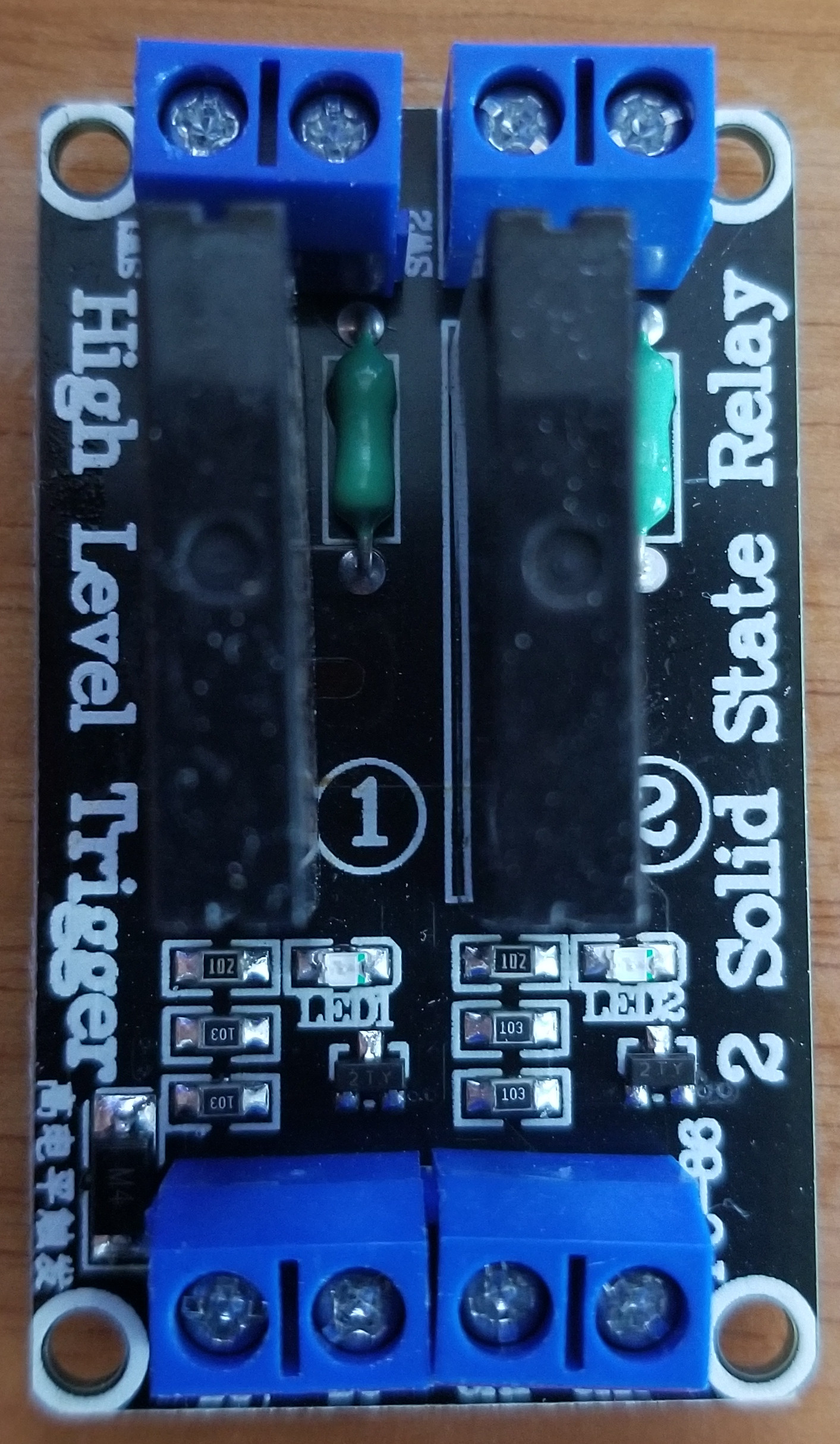
Innocent me, I never thought of testing these out before using them(they look simple enough it’s hard to mess them up), so I simply hooked them up to 5V to DC+, GND to DC- and a ESP8266 GPIO to CH1. Then I plugged in a motor on the SSR output, flipped the GPIO and expected it to move and stop…it did not.
I suspected the module was faulty, so I tried another one. And another one. None of them seemed to work…They lighted up the LED, but nothing in the world made the output work. So I now suspected the ESP8266…I removed it, by simply hooking and 5V to CH1 and CH2, hooked up the AC to the output and lo and behold, it didn’t work either.
It also did strange things, like, if CH1 and CH2 (the control inputs) were left floating, the LED would light up (but the output wouldn’t work). If CH1 or 2 was connected to GND, the LEDs would turn off…but also no output.
Next up, I suspected 5V was not enough, after all I measured the voltage at the G3MB pins and it was 4.4V due to a diode in series (more on that later)…I cranked up the voltage…5.5 and it didn’t work…6…it didn’t work…6.5 and …it started working! The light bulb I hooked up turned on when I put a high value on CH1 and it turned off otherwise. That was great, but why was it working at that voltage and not 5V?
I reviewed the publication on Mercado Libre, it was clear it was meant to work at 5V.
This should’ve been the time when I was supposed to return these clearly faulty boards untouched. That would’ve been the smart choice.
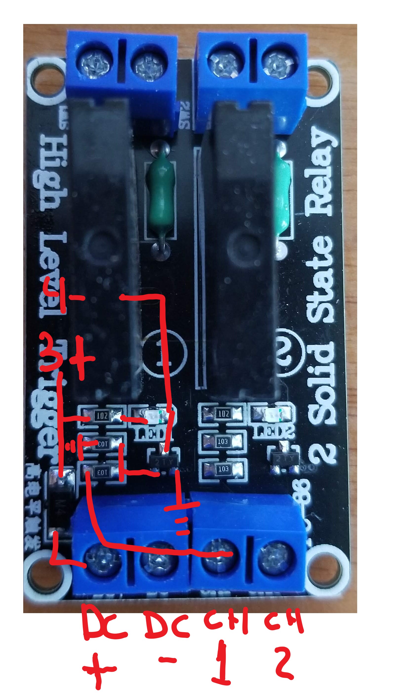
Instead, I made a schematic by testing points…it looks like this:
I looked online for G3MB circuits and what do you know, I found just the thing:
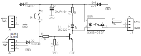
That looks very similar to what I traced on the board, there’s no zener diode (ZD1), D2, S1 or C1 but the rest is pretty much the same. So…why is it not working?
Next up, I started double checking components. The resistors marked 103 are 10K and 102 is 1K, the LEDs were obviously working fine, the G3MB-202P were fine, the resistance matched what the datasheet said. Even the input diode (D1) was ok…so, all that was left was the transistor (T1), it’s marked as “2TY”. I googled that and found the datasheet, which indicates this is a S8550 TRANSISTOR (PNP).
And here lies the problem: This circuit requires a 2N2222 or equivalent (i.e. 2N3904) NPN transistor. The current flows the “other way around” on a PNP transistor, so this was never going to work as advertised.
I bought four boards, with 8 transistors in total, they were all wrong.
To test my theory I lifted up one of the transistors and Frankenstein’ed in a 2N3904.
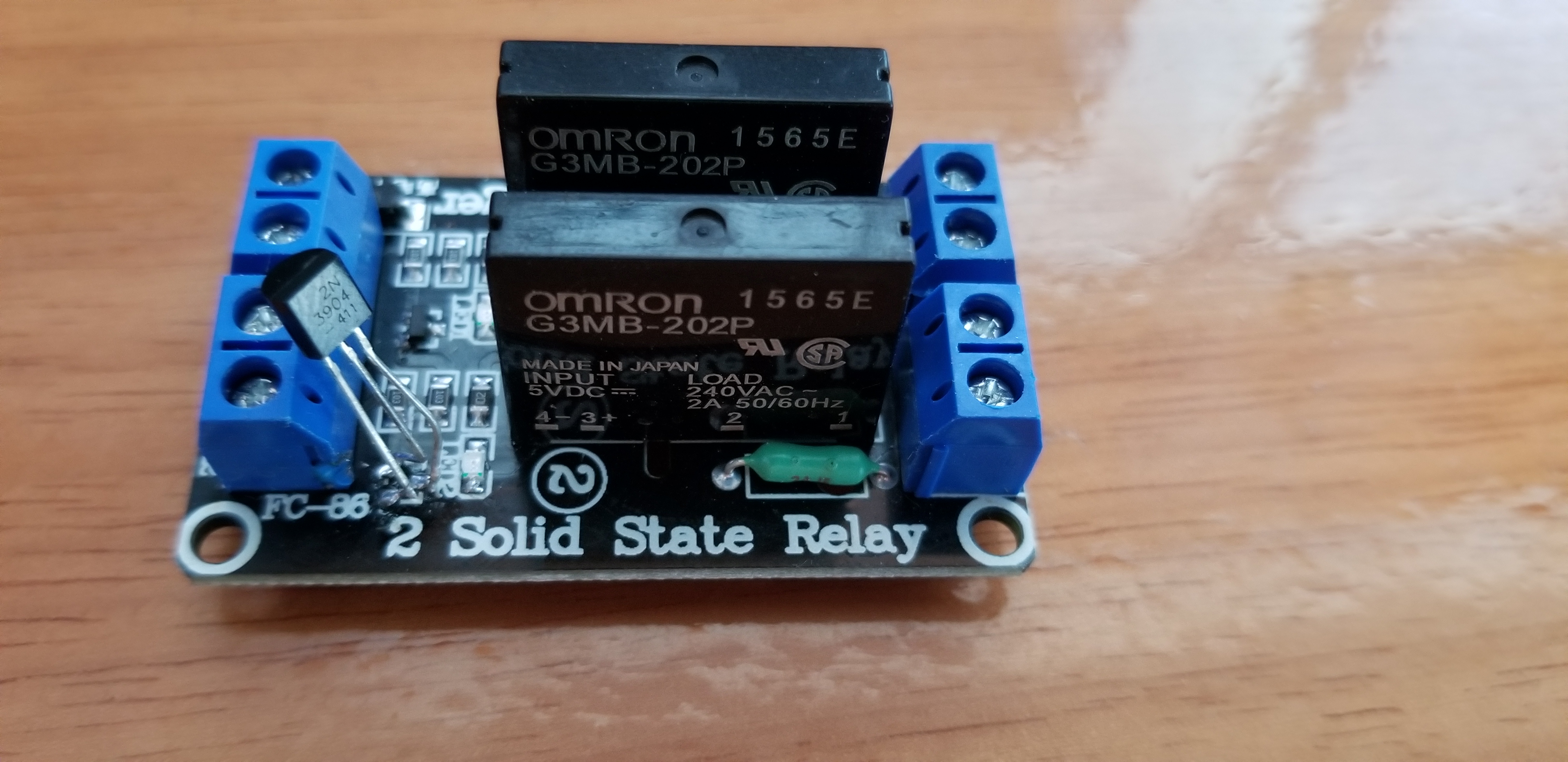
Sure enough, it did what it was supposed to. 5V on CH1 turns it on, GND turns it off. Light bulb or motor or anything that uses AC can be controlled just fine.
The epilogue on this pointless story is that after plugging it in a Sonoff Basic R2 modules, it was preventing it from booting up, because the pin you have available on the Sonoff must be kept high on boot (it’s used to indicate the boot mode to the bootloader)…So before I was finished I had to remove R2, and add a 2K pullup between 5V and CH1. Then, I was finally done.